
In most circumstances, this path is not required because the use of software flow control is common with most modern serial devices. LoopBack provides connectors for popular relational and NoSQL databases. Likewise, your connected device will use pin 8 (CTS - Clear To Send) to tell the computer when information can be sent.īy connecting pins 7 and 8, we are sending the RTS signal to the CTS pin allowing us to verify that the com port is able to handle hardware flow control.
#Loopback connector code
Apex Designer allows you to edit generated code as well as add new code.

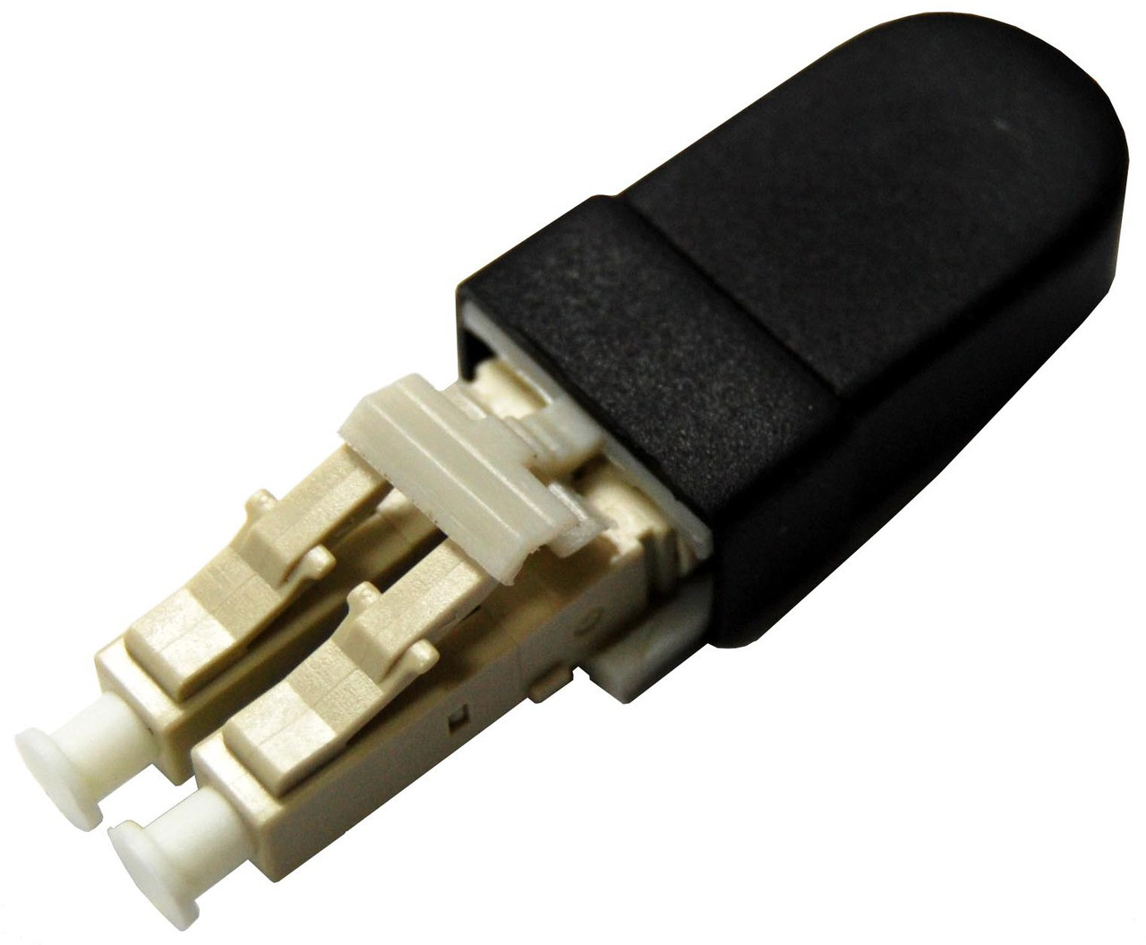
In a normal RS-232 connection with hardware flow control checked, the computer will use pin 7 (RTS – Request To Send) to tell the connected device when information can be received. Creating a Loopback connector is a pure code part of the low-code experience. A loopback cable is also known as loopback plug or loopback adapter, which is a plug used to test physical ports to identify network issue. This path handles the flow of information between the computer and device, similar to path 1. In most applications, you will only need to connect pins 2 and 3 to test the functionality of a DB-9 serial port. By connecting pin 2 (Rx- Receive Data) to pin 3 (Tx- Transmit data), we are able to verify that the computer is able to send and receive information through a serial connection.

This path handles the actual information being transmitted across the serial connection. This handshake, for the most part, just verifies that the modem, or other DTR / DSR enabled device, is turned on and active.īy connecting pins 1, 4, and 6, we are taking the DTR signal and sending it to the DSR pin and the CD pin allowing us to verify that the computer is able to communicate with a modem.Īdditionally, you can connect pin 9 (RI - Ring Indicator) to this path to verify that the computer is able to detect when a call is coming in from the modem. The computer will then use pin 4 (DTR - Data Terminal Ready) and pin 6 (DSR – Data Set Ready) to create a handshake between the computer and modem. The modem will use pin 1 (CD – Carrier Detect) to tell the computer that there is a carrier tone detected or it has made a connection with a second modem. Pinouts > Serial interfaces cables and converters scheme. It is important to understand the purpose of each connection for troubleshooting serial connections. Pinout of Serial (Female D9F) Loopback for PC-check and layout of 9 pin D-SUB female connectorthis adapter is used for diagnostic of rs-232 de-9 serial port. In comparison to normal loopback links, where one NIC is connected with another NIC on the same appliance, the self-loopback does realize the loopback inside the same NIC. OS2 MPO Fiber Optic Loopback Adapter, 12-Core MPO Connector Singlemode 9/125 Test Plug for QSFP+ Transceiver Testing Applications or Network restorations. If you dont want to make your own plugs, you can always purchase our serial and parallel loopback plugs. The DB-9 connector as the following 9 pins. The above tables and wiring diagram outlines the required connections to create a loop back plug. Specifications for Serial Loopback plug Product Code PM012 The serial port on IBM compatible PCs conform to the RS232 electrical standard and use a male DB-9 connector.


 0 kommentar(er)
